Patent · US 11,318,299 B2 · granted 2022
A blueprint for a high-channel visual implant
Thousands of glass-coated microwires, driven by the kind of chip that runs a display, designed to stimulate the nerve fibres that carry vision from the eye to the brain.
Cancer Neurotechnology Lab
14 October 2026 · 9 min read
Most attempts to restore sight with electronics face the same arithmetic. Natural vision relies on very large numbers of cells and nerve fibres. An implant with a few hundred contacts can only ever paint a very coarse picture.
US Patent 11,318,299, filed by the Francis Crick Institute, sets out a design aimed at much higher channel counts.[1] Its inventors are Romeo-Robert Rácz, Gabriella Rácz and Andreas Schaefer. The patent describes an implant built from very fine glass-coated wires with nanostructured tips, driven by the kind of chip that normally runs a display, and positioned so that each wire can stimulate the nerve fibres leaving the eye.
The problem it addresses
The patent opens with the scale of the need. It cites an estimated 39 million people affected by blindness worldwide, and notes that stimulating the retina can produce useful visual sensations in people with retinitis pigmentosa, but not when the retina's output cells, the ganglion cells, have been lost.[1] It names the optic nerve, a relay station in the thalamus called the lateral geniculate nucleus, and the visual cortex as feasible targets further along the visual pathway.
It then identifies two technical limits of existing approaches. First, retinal devices at the time offered several hundred stimulation or recording sites, while the patent argues that detailed vision may need on the order of 10,000 or 100,000 cells or fibres to be stimulated. Second, electrodes with high impedance at their tips need larger currents and extra amplification. The patent notes that heating of tissue scales with the square of the current, so many small currents through narrow electrodes may cause less damage than a few large ones.
What the patent describes
The first claim defines the core of the invention.[1] A visual implant has an array of micro-electrodes, including at least two that stimulate. Each has a core of conducting material, insulating material around it, and a layer of metal or metal-oxide nanostructures on its tip at the end that meets the tissue. An integrated circuit controls the pattern of stimulation current through the array.
Further claims add detail. They cover electrodes 30 micrometres or less in diameter; gold nanostructures; an iridium oxide coating; glass insulation; flexible electrodes; wires made by the Taylor–Ulitovsky method, in which metal is drawn inside molten glass; sharpened, angle-polished tips; a pixel display driver as the integrated circuit; and driving current through a two-dimensional pattern of electrodes simultaneously.
The description also explains how the far end of each wire connects to the chip. Small gold bumps are grown on the wire ends. Because these bumps are made of soft nanostructured gold, they can deform when pressed against the chip's contacts, so in a very high channel-count array the wires can be connected simply by pressing the bundle onto the chip.
Two ways to get the picture in
The patent describes two versions of the system.[1]
In the first, a head-mounted camera captures images and a processor turns them into a stimulation pattern. The pattern is sent wirelessly to the implant, which also receives its power wirelessly, for example by radio-frequency or inductive transfer.
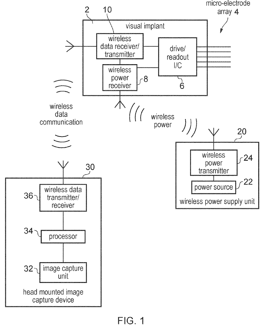
The first version. A head-mounted camera and processor (bottom left) send stimulation patterns wirelessly to the implant (top), which drives the micro-electrode array. A separate unit supplies power wirelessly (right).
Drawing reproduced from US 11,318,299 B2 (FIG. 1).In the second version, the camera and processor are built into the implant itself, inside the eye. The patent points out an advantage: the eye's own muscles would then aim the camera wherever the person looks.
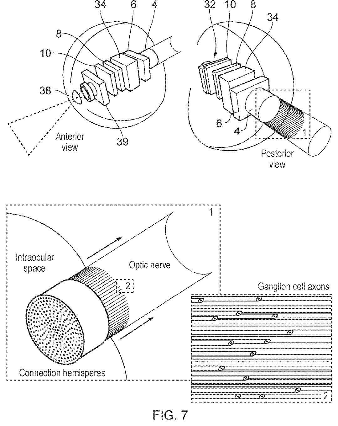
Inside the eye. The fully integrated version sits in the eye with its own optics (top). Its microwires enter the optic disc in parallel with the ganglion cell axons, which also run side by side (bottom).
Drawing reproduced from US 11,318,299 B2 (FIG. 7).The patent also describes how a processor might translate an image into stimulation: for example, detecting edges and stimulating the electrodes that correspond to them, so a user could perceive the outlines of objects, or adjusting the position, frequency and strength of stimulation according to shading or colour. These are described as options, and the patent presents the implant as a research platform for working out which mappings are useful.
Why the optic disc
The patent's central anatomical argument is a matching of shapes.[1] At the optic disc, the axons of the retina's ganglion cells run in parallel, side by side. A bundle of straight microwires is also parallel. Inserting the wires along the fibres should give an efficient interface, and stimulating the fibres directly means the implant does not depend on the retina's own circuitry, which the patent notes would simplify development.
Sensing as well as stimulating
The same electrodes can be given different coatings to sense chemistry. The patent describes sensing electrodes for glucose or pH, which it suggests could help track diabetes, a cause of sight loss. It also mentions, as possibilities, detecting amyloid beta in the retina in connection with Alzheimer's disease, and detecting the protein GFAP, associated with traumatic brain injury and brain tumours such as glioblastoma, by decorating the nanostructures with an antibody.[1] These are described as options in the patent, not demonstrated results.
The experiments in the patent
The patent includes two feasibility experiments.
Stimulating neurons in a mouse. The team used a genetically modified mouse whose neurons fluoresce when active, and imaged them with a two-photon microscope while passing current through a micro-electrode array placed in the olfactory cortex, as the patent describes it.[1] With stimulation off and on, the same field of view showed clear increases in activity in labelled cells, including some at a distance from the probe tip.
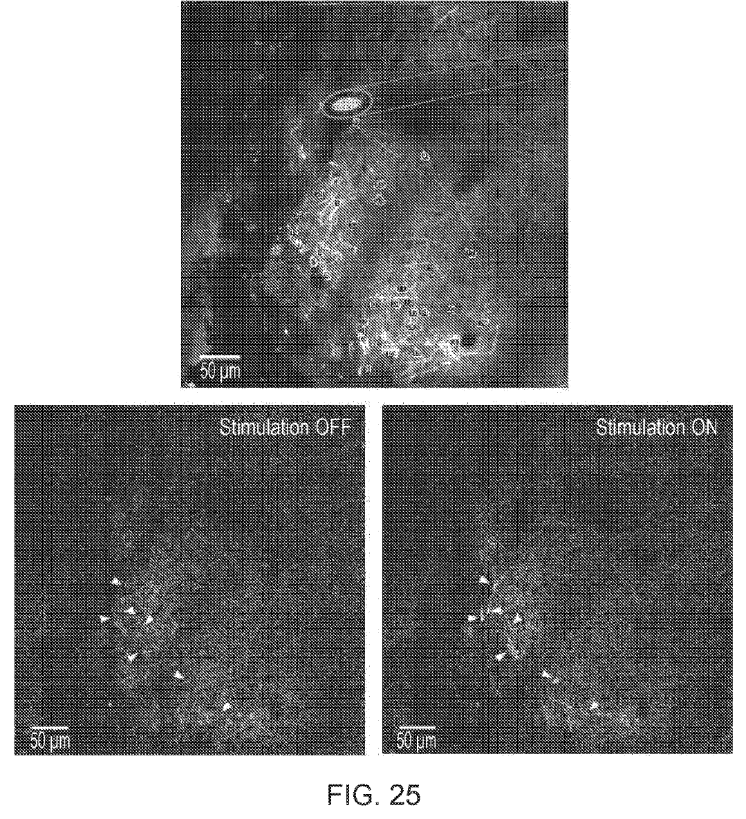
Stimulation, seen. The probe tip is outlined in the top image. Cells marked with arrowheads are brighter with stimulation on (bottom right) than off (bottom left).
Drawing reproduced from US 11,318,299 B2 (FIG. 25).Currents from 20 to 50 microamps were tested. The patent reports that some cells responded to very small currents and others only to larger ones, that activity could be elicited reliably across this range, and that neurons responded to a 50-microamp pulse regardless of where they sat relative to the stimulation site.
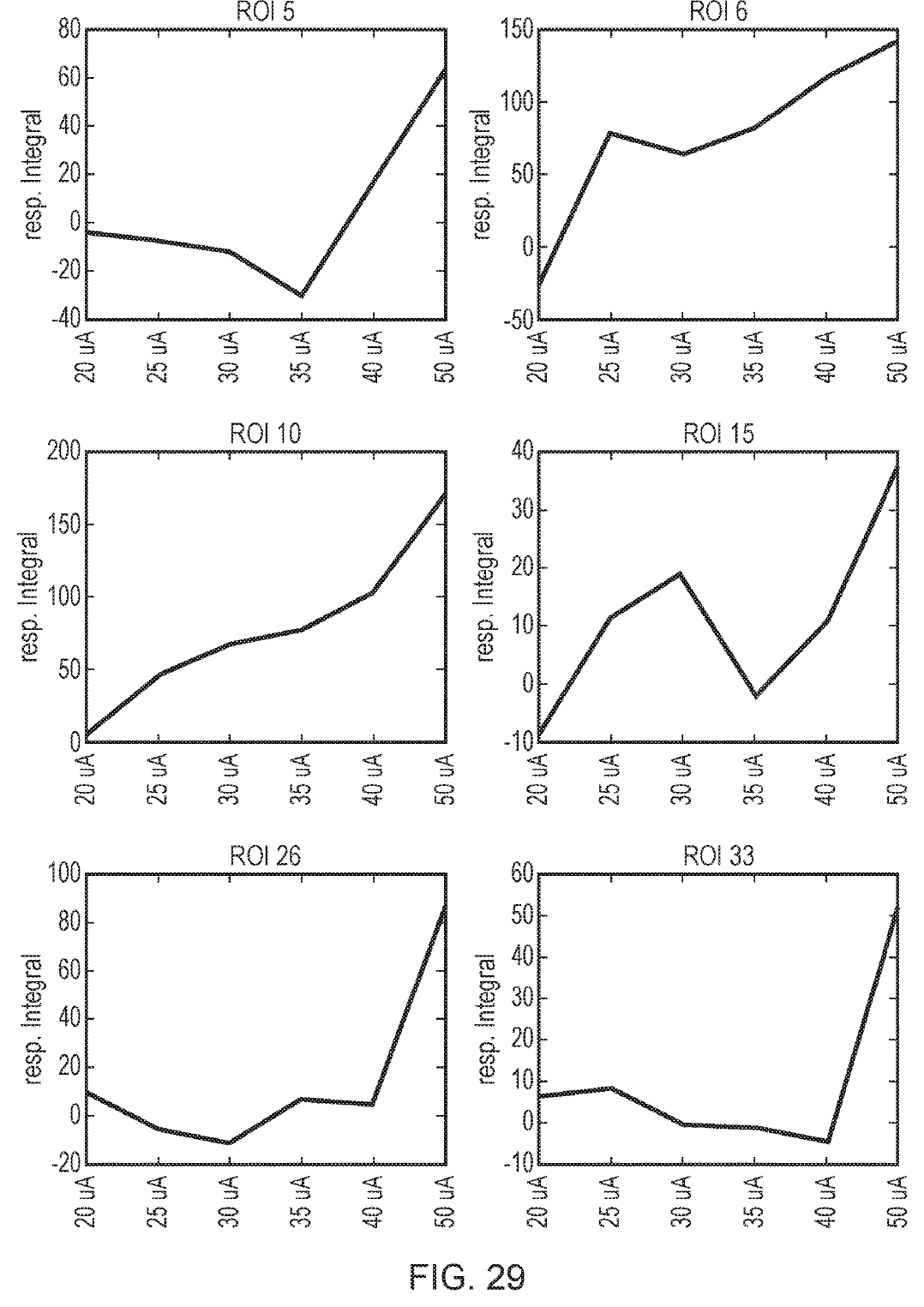
Responses grow with current. Each panel is one region of interest. The strength of the response is plotted against stimulation current from 20 to 50 microamps.
Drawing reproduced from US 11,318,299 B2 (FIG. 29).Stimulating the optic nerve in a sheep's eye. In an in vitro preparation, a 10-channel stimulating probe made of the patent's gold-tipped glass-coated wires was inserted into the optic nerve head of a sheep's eye. A 16-channel recording probe of the same kind was placed in the optic nerve about 2 centimetres from the eyeball.[1] When trains of ten 1-millisecond pulses were delivered at 40 microamps, and again at 165 microamps, the recording probe detected a clear response downstream. The patent presents this as demonstrating the principle that signals can be sent along the optic nerve by stimulating at the optic disc. It also shows an array of about 1,000 micro-electrodes positioned over half of the optic nerve head, and notes that the nerve head would have room for two to three times more channels.
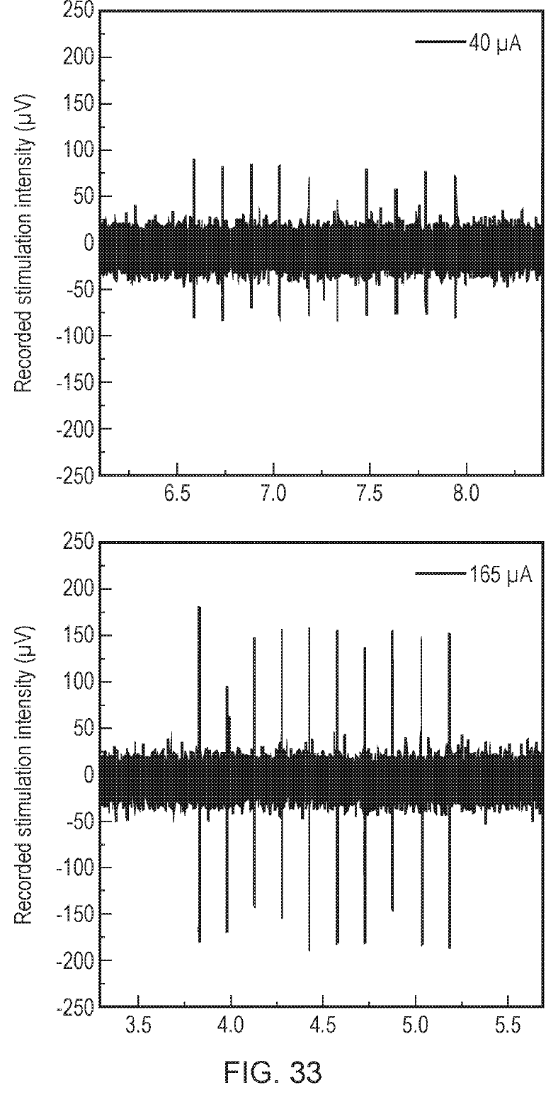
A signal travels down the optic nerve. Ten stimulation pulses at the optic disc of a sheep's eye produce ten responses recorded about 2 cm along the optic nerve, at 40 microamps (top) and 165 microamps (bottom).
Drawing reproduced from US 11,318,299 B2 (FIG. 33).What a patent is, and is not
- What it shows. The patent sets out a specific design for a high-channel visual implant and the methods to build it, with feasibility experiments in a mouse brain and in a sheep's eye in vitro.[1]
- What it does not show. It does not report that the device restores vision, any test in people, long-term implantation, or safety data. Several features, such as image processing and chemical sensing, are described as possible embodiments rather than tested results.
- What defines it. The scope of protection is set by the granted claims, which should be read in full on the public register.
How it connects to our other work
The electrodes at the heart of this patent are the same family as the jULIEs probes, whose recording and stimulation performance was later reported in a peer-reviewed paper,[2] and as the probe described in an earlier patent by overlapping inventors.[3] Read our guide to the electrochemical probe patent.
Sources
- [1]Rácz R-R, Rácz G, Schaefer A. Visual implant. US Patent 11,318,299 B2, granted 3 May 2022; assignee The Francis Crick Institute Ltd. patents.google.com/patent/US11318299B2/en
- [2]Rácz RR, Kollo M, et al. jULIEs: nanostructured polytrodes for low traumatic extracellular recordings and stimulation in the mammalian brain. Journal of Neural Engineering 19(1):016041 (2022). Open access. doi.org/10.1088/1741-2552/ac514f
- [3]Rácz R-R, Kollo M, Schaefer A. Electrochemical probe. US Patent 10,768,139 B2, granted 8 September 2020; assignee The Francis Crick Institute Ltd. patents.google.com/patent/US10768139B2/en
How to cite the original work: Rácz R-R, Rácz G, Schaefer A. Visual implant. US Patent 11,318,299 B2, granted 3 May 2022. Assignee: The Francis Crick Institute Limited. Priority: GB 1801320.1, filed 26 January 2018.
Drawings are reproduced from the published US patent, a public record, and credited to it. Captions have been rewritten for a general audience; see the patent for the full description of each figure.
This summary is written for public understanding and is not medical advice.